Electrical
Boxes & switches
Sockets, switches and distribution boards — box positions straight from the model.
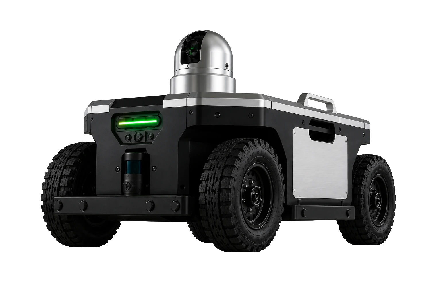
The marking robot
The PRALEX robot drives autonomously across the construction site, localises itself against the model and projects the planned marking points with a green laser — as a demonstrator for the PRALEX ecosystem.
Design study · concept demonstrator
Why
On the construction site there's constant measuring, marking out and setting out: sockets, drill holes, partition walls, service runs. Much of it by hand, point by point — slow and error-prone.
Yet the positions are already in the BIM model. The robot transfers them straight onto the site — fast, repeatable and without reinterpreting the plan on location.
In use
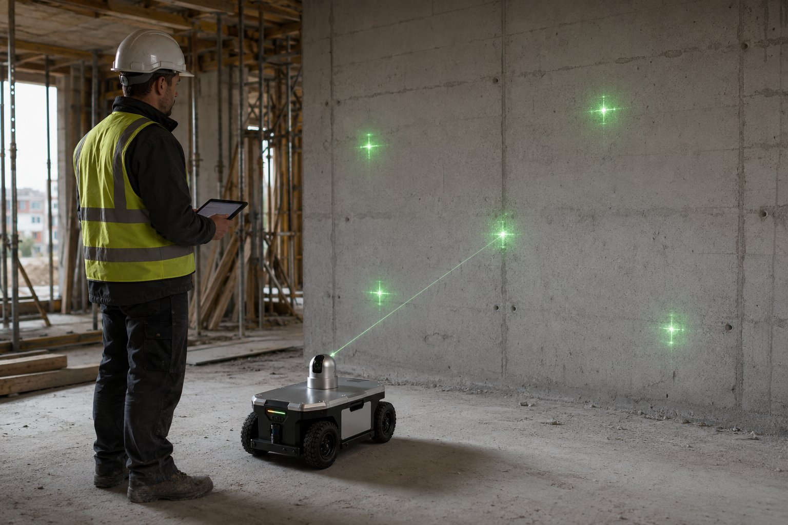
Instead of transferring plans onto the site by hand, the robot places the points exactly where they are planned in the BIM model.
Sockets, switches, openings, fixing points — projected onto the wall as a green laser cross, at the planned position. The worker marks or drills right at the point.
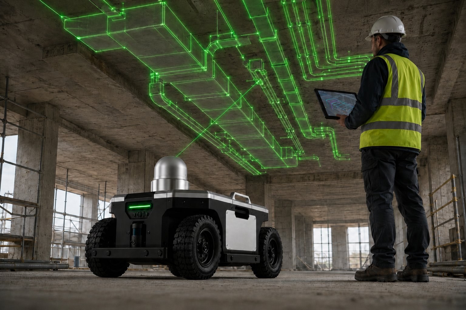
Service runs and fixing points for ventilation, piping and suspended ceilings — projected onto the structural ceiling. The building services become visible before they are installed.
Sockets and openings are only the start — anything that has a position in the model can be marked.
Electrical
Sockets, switches and distribution boards — box positions straight from the model.
Mounting
Fixing points for brackets, rails and consoles of all kinds.
Structural shell
Recesses and openings for cables, pipes and ducts.
Drywall
Axes for stud framing and partition walls — including on plasterboard.
Building services
Routing and suspension points for ventilation, plumbing and electrical.
Reference
Metre lines, reference lines and axes in the room.
On concrete, masonry, plasterboard and screed — on wall, floor and ceiling.
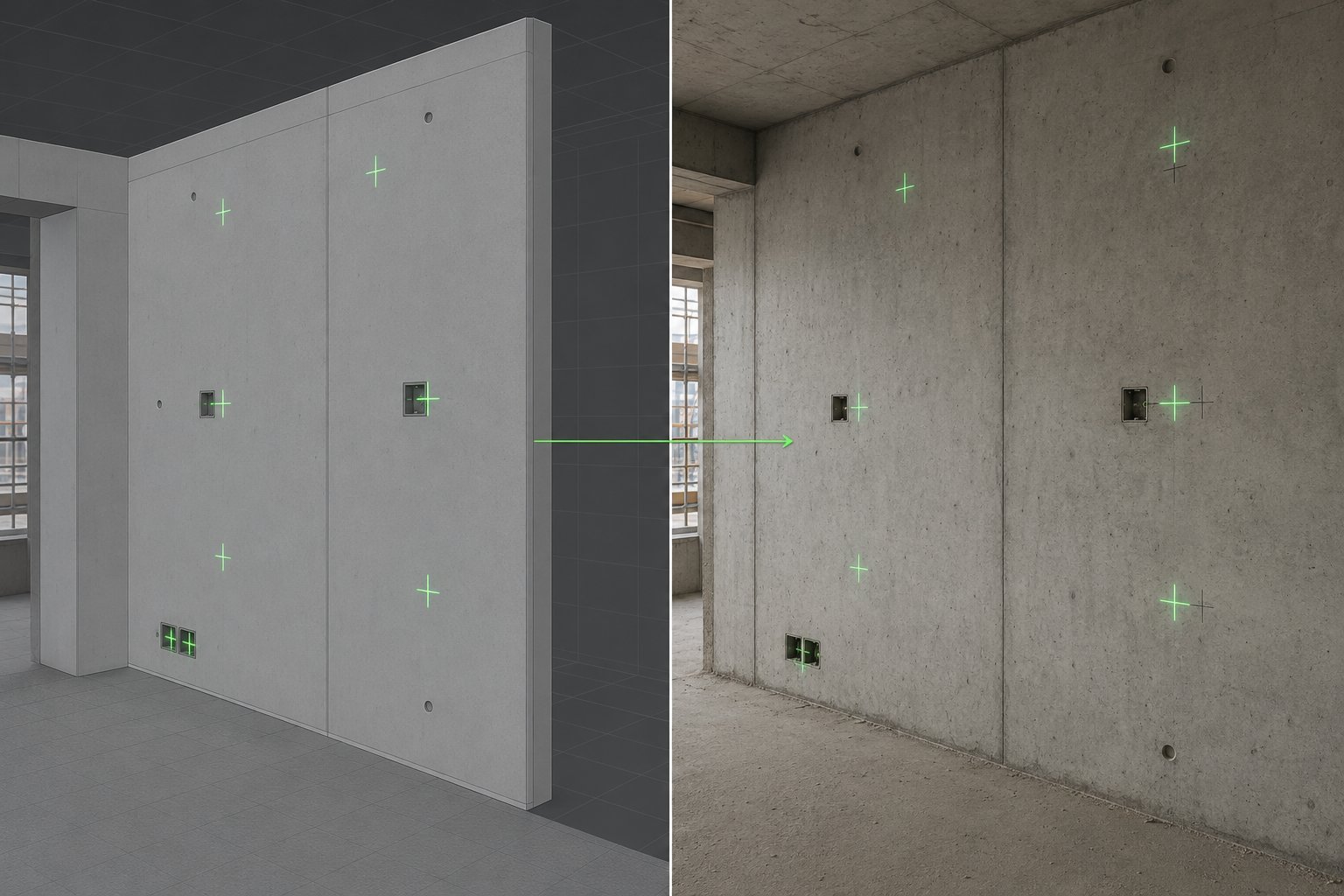
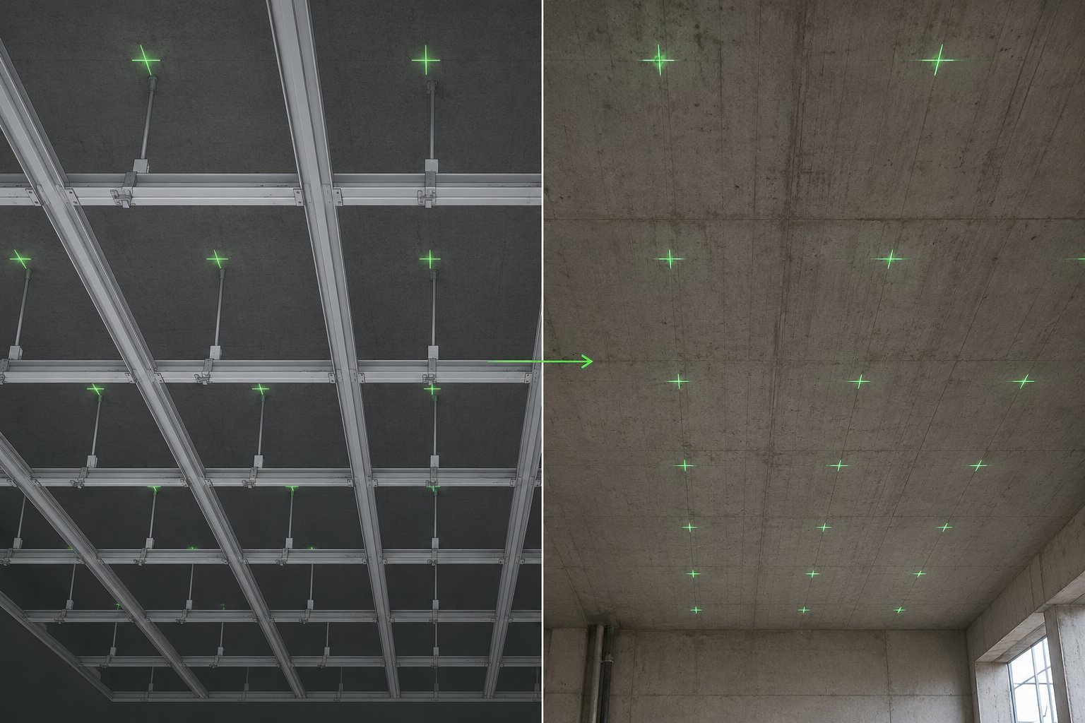
Model → reality
The same points — once in the model, once on the wall. What is planned gets transferred onto the site.
On the left the points in the BIM model, on the right the same points as green laser crosses on the concrete wall.
The suspension grid of the suspended ceiling from the model — transferred onto the structural ceiling as a grid of points.
Workflow
Four building blocks bring the plan onto the site — from the BIM model to the laser cross on the wall.
1 · BIM
Room geometry and planned points come from Revit (via PRALEX for Revit) or from any tool that exports IFC — as the open Robotic Construction Format (.rcf).
2 · Planning
Computes stations and route: where the robot has to stand to reach every point.
3 · Coordination
Stores the jobs and distributes them — on the construction site or in the cloud.
4 · On site
A web app (PWA) controls the robot on site: load the job, drive it, mark.
PRALEX Planner
PRALEX Planner is our own software. From the points in the BIM model it computes the complete robot job: where the robot has to stand — and in which order it drives to the stations.
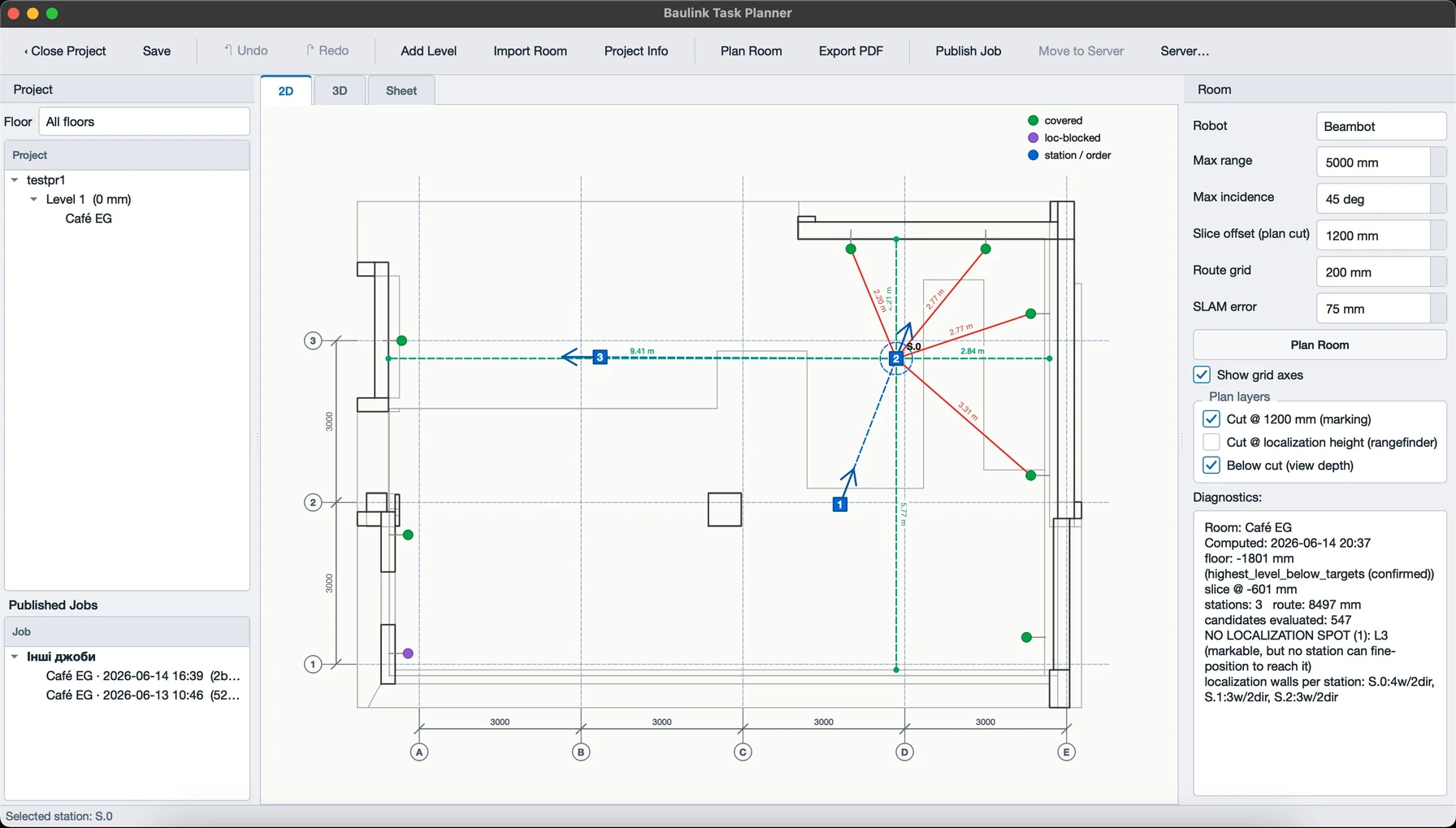
Stations
From each station the laser reaches only some of the points — limited by range, angle, line of sight and free standing space. The planner picks the fewest stations that together cover all points.
Route
The stations are ordered into the shortest drive — computed as the real travel distance around walls, not as the crow flies. So the robot drives as little as possible.
Diagnostics
Points that no station can reach safely are flagged — instead of being silently dropped. So it's clear in advance what the robot can manage.
All visible in the 2D floor plan and the 3D model — floor by floor. Desktop app for Windows and macOS.
Platform
The marking robot builds on the modular PRALEX platform — with a shared navigation module of 3D LIDAR, laser distance sensor and AI camera. The same base carries other roles too.
Build
A compact mobile platform with the building blocks that make marking on the construction site possible.
Drive
Four-wheeled chassis for the construction site — designed for dust, debris and uneven ground.
Marking
Pan-and-tilt head with a green 520 nm laser that indicates the points on wall and ceiling.
Localisation
Captures the room and helps align the robot's position with the model.
Perception
Supports alignment and checking — and makes the marked point traceable.
Operation
Load the model, select points, drive — the site operates the robot via a tablet.
Safety
Emergency stop and status display on the device; laser safety is part of the design.
Concept demonstrator in development · accuracy is a development goal, not a guaranteed specification.
Part of the whole
The robot shows what's possible. The goal behind it is an open platform for construction robots and machinery — with a shared data format, coordination server and modular robot base.